The Tooth Rock Viaduct solved the problem of carrying traffic around Tooth Rock, a towering basalt cliff. (Oregon Department of Transportation)
What is a Viaduct?
This drawing shows the Mitchell Point Viaduct spanning a cleft.
(Library of Congress, Prints & Photographs Division, HAER ORE, 26-TROUT.V1- (sheet 13 of 27))
The Merriam-Webster Dictionary defines Viaduct as
"a long elevated roadway usually consisting of a series of short spans supported on arches, piers, or columns."
Spanning a Cleft
Designers met a significant engineering challenge at the west approach to the Mitchell Point Tunnel. They had to span a long gap from a rock ledge to the west portal of the tunnel. Between the two was a cleft, or split, in the rock of Mitchell Point that consisted of a steep slope of talus, or unstable rock fragments. Their solution was to construct a 192-foot viaduct made up of several short concrete slab bridges featuring piers at the ends of each separate span. A photograph of the Mitchell Point Viaduct below highlights this engineering feat.
Raising the Roadbed
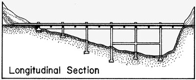
A combination of geography and land ownership caused another engineering problem that designers solved with viaducts. The route of the road to the west and the east of Multnomah Falls followed a razor-thin path between the steep mountainside to the south, and the Oregon-Washington Railroad and Navigation Company (now Union Pacific Railroad) main track to the north along the edge of the Columbia River. Engineers considered building a typical retaining wall but even a small amount of cutting and filling at the toe of these steep slopes, tenuously tied together with underbrush and timber, could have caused avalanches to fall on both the highway and the railroad tracks.
 This drawing shows a viaduct that raises the roadbed.
(Library of Congress, Prints & Photographs Division, HAER ORE, 26-TROUT.V1- (sheet 13 of 27))
This drawing shows a viaduct that raises the roadbed.
(Library of Congress, Prints & Photographs Division, HAER ORE, 26-TROUT.V1- (sheet 13 of 27))
Again, the solution was to construct viaducts, anchored to the slopes and resting on unequal length columns. The viaducts, rising slightly from the hillsides, loomed over the railroad tracks but averted disaster by maintaining vertical clearances for rail traffic. Slope stability proved to be a problem in 1921 when storm damage led to the need for support walls to be poured behind every other column along the East Viaduct.
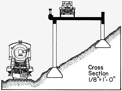
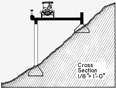
Skirting Hillsides
Engineers used a relative of the viaduct to skirt hillsides in several locations along the highway. Half-viaducts were designed much like viaducts with columns of unequal length. However, instead of the inside part of the structure being elevated from the hillside, it consisted only of footings and the inside elevations were anchored into the hill or masonry wall. With the half-viaducts being inconspicuously anchored directly to the hillside, travelers on the highway often thought that they were driving on a normal surface road instead of on a partially elevated engineered structure.
 This drawing shows a half-viaduct that skirts a hillside.
(Library of Congress, Prints & Photographs Division, HAER ORE, 26-TROUT.V1- (sheet 13 of 27))
This drawing shows a half-viaduct that skirts a hillside.
(Library of Congress, Prints & Photographs Division, HAER ORE, 26-TROUT.V1- (sheet 13 of 27))
Significant viaducts, according to the Historic American Engineering Record, include:
The West Multnomah Falls Viaduct is 400 feet in length and consists of twenty 20-foot reinforced-concrete slab spans. The deck is supported by two parallel rows of 16-inch square columns that stand 17 feet 6 inches apart.
The East Multnomah Falls Viaduct is identical to the West Multnomah Falls Viaduct, except that it is 860 feet long. Both structures were completed in 1914.
The 560-foot Crown Point Viaduct, which consists of 28 20-foot reinforced-concrete deck slabs, averted unnecessary excavation or fill to make room for a 7-foot sidewalk and curb. The design also included a 4-foot concrete outer railing and concrete light standards to illuminate Crown Point at night.
The Tooth Rock and Eagle Creek viaducts, at 224 feet in length, carry the highway around the towering basalt cliff called Tooth Rock before dropping down to Eagle Creek. Only the railing treatment differentiates their design. The Tooth Rock Viaduct uses a concrete spindle and cap design, while the Eagle Creek Viaduct uses a masonry rail and concrete cap design.
The 50-foot Ruthton Point Viaduct, consisted of three reinforced-concrete deck girder spans and carried the highway near a promontory west of Hood River. It used a simple standardized concrete railing panel and cap. The structure was reconstructed in recent years to be part of a pedestrian and bicycle accessible trail along once abandoned sections of the highway.
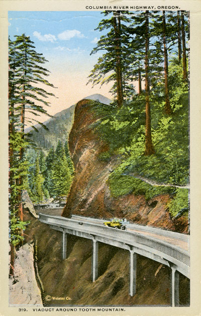
A vintage postcard shows the viaduct at Tooth Rock. (Oregon State Archives, Private Donation Postcards)
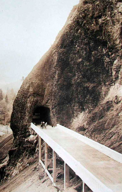
A horse-drawn wagon crosses the Mitchell Point Viaduct heading west after exiting the Mitchell Point Tunnel. (Curious Gorge Blog)
A viaduct carries the highway around Vista House at Crown Point. (Oregon State Archives, Private Donation Postcards)
Credit
Most of the information on this page was adapted from the Historic American Engineering Record, National Park Service, Elaine G. Pierce, 1995. (Library of Congress, Prints & Photographs Division, HAER ORE, 26-TROUT.V1- (sheet 13 of 27))